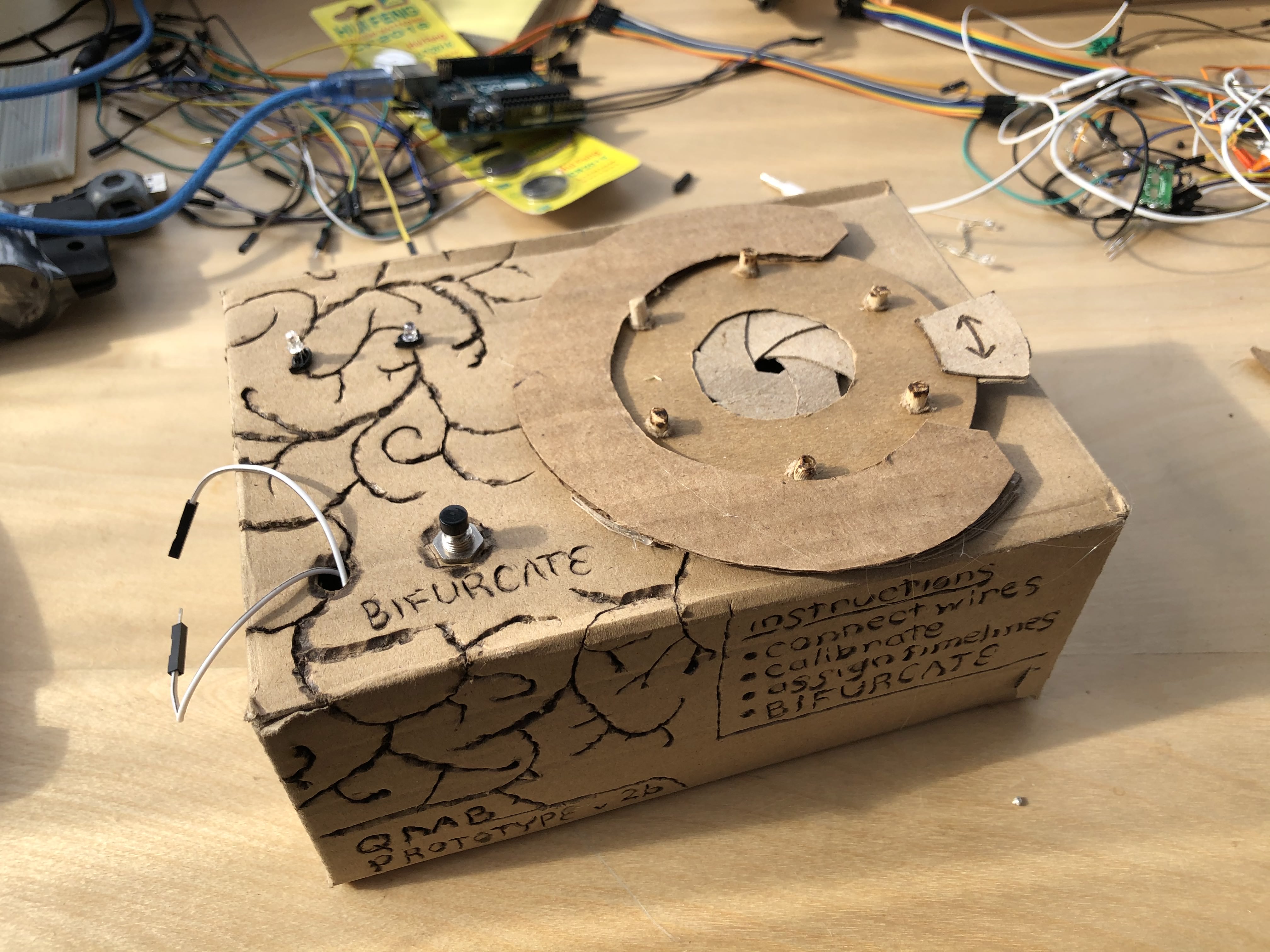
Quantum Coin Flip Device
Over the past few months, I've been working on building tools to connect human decisions with the outcomes of quantum measurements. The goal is to allow people to let their decisions be chosen using the many-worlds interpretation of quantum mechanics, which will end up creating parallel realities where all outcomes occur. You can read this post to learn more about the idea and how I built a web-based Quantum Multiverse Bifurcator.
The main drawback of my webapp is that it relies on being connected to the internet to request a quantum measurement from an experiment being run by this quantum computation research group in Australia. Ideally, I'd like to be able to make such a quantum measurement myself to make it more accessible wherever I go.
There are many examples of various quantum measurement devices on the web, but most of them are more sophisticated and would be fairly expensive to build. All I need is a device that can make a simple binary measurement from the outcome of a quantum event. So I set about trying to design something cheap and simple that still maintains true quantum randomness.
Concept
The simplest kind of quantum measurement is probably shot noise, or the variability in the number of photons detected when measuring light with a photodetector. A photodetector is just any device that absorbs light and converts the light it absorbs into an electrical signal. Photodetectors are used in a bunch of things, like if you've ever seen a nightlight that only turns on when its dark, or if you've ever seen your phone/computer automatically adjust its brightness.
The reason that this is a quantum measurement is that the light field that is being absorbed exhibits quantum fluctuations, which cause the number of photons present to vary. Therefore, the exact amount of electricity generated by the photodetector is also varying slightly even if the average amount of light stays the same. To detect the quantum effect one needs to observe the variability in the electrical signal of the photodetector.
Unfortunately, measuring the exact electrical signal with the kind of sensitivity needed to pick up on the quantum signals normally takes a pretty sophisticated device. That would be costly and make this measurement device a little impractical. So I wanted to simplify the machinery needed to make this measurement.
Given that I only really need to generate a binary outcome (a coin flip), I knew that I could get away with a circuit that just goes on when the measurement is beyond some threshold. The catch is that its a little bit difficult to calibrate exactly where the cutoff should be. In addition, it's possible that the source of the variability could be non-quantum if the device isn't set up properly. There are many other sources of apparent randomness that don't come from quantum mechanics and I wanted to make sure to isolate my system from those.
To alleviate these issues, the design I chose actually creates two quantum measurements of the shot noise from two photodetectors. It then compares the signal from each measurement at a specific point in time and either turns on or off an LED depending on which measurement is greater. This allows for the circuit to really only use 4 components while still transmitting a quantum signal to a binary outcome.
The last important thing is that you need to be able to control for the variation in the electrical components of the circuit, which could affect the measurement but are non-quantum. To control for this, I can calibrate the amount of light hitting each photodetector to make the measurement go either way with almost exactly 50% probability. And the amount of light can be lowered further and further to turn down the contribution of classical effects on the randomness.
With this basic concept, the only thing left to do was to try to build it.
Circuit
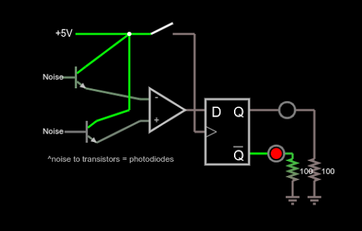
After asking both physics and electronics stack exchanges with little results, I came up with the following circuit

To view the circuit in simulation go here. On the simulation site each time you close the switch one of the LEDs should light randomly. Below I will walk through each of the subcomponents in a little more detail.
Step 1. Generate slightly varying voltages from two photodiodes
The first step is to make a very simple photodetectors using photodiodes. The photodiodes act like little dams that prevent the flow of electricity (called current), but which let more electricity through when light is shined on them.

In the circuit, I connect the photodiode to a between the plus and minus ends of the battery with a resistor after it. This causes there to be a voltage across the resistor, which then fluctuates as the light hitting the photodiode varies. At low enough light, the variation is mostly quantum mechanical in nature.

One important point is that there can also be classical noise in this type of circuit, largely due to thermal noise changing the resistivity of the resistor. To overcome this, I got a tip from a physicist friend of mine to use a very large resistor. This should ensure that the thermal variation is small relative to the variation from the quantum effects in the photodiode.
*Note: When I built the circuit simulation on falstad's circuit simulator, I wasn't able to put in a photodiode directly. Instead, I mocked those components using a transistor and random noise source. The rest of the simulation circuit looks like the real prototype though.
Step 2. Comparing the photodetectors
The next part of the circuit performs an amplification of the signal difference between the two photodetectors. This is accomplished using an op-amp comparator. The comparator is a widely available circuit that works to

So whenever the first photodiode's voltage is just slightly higher than the second one's voltage, the output of the comparator is high (+3 volts in my circuit). And whenever the second signal is higher the voltage goes low (0V in my circuit). This signal is varying all the time though as the two detectors vary back and forth. So to persist the measurement we need one more component.
The D-Latch (flip-flop)
Given a time varying voltage, we need a way to detect whether the voltage is high or low at one instant and then persist that value for a long period of time. There are a number of ways to do this, but one of the simplest is with a "latch" circuit. There are many kinds of latches, but they all take an input and then hold an output value until the circuit is reset.

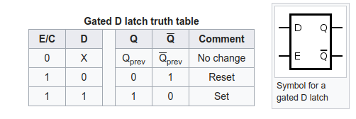
I used a D-Latch, which takes an input signal and stores it at the moment a "trigger" input is pushed. Then the D-Latch holds that value and outputs it until the trigger is pushed again. The output is referred to as Q in the diagram. In addition, most D-Latches also output the opposite of Q (called Q') at the same time.

The signal for my D-Latch was just the output from the comparator. I had a manual switch that set the trigger. If the output from the comparator is high when the trigger is pushed, then the D-Latch will hold Q at high and Q' at low. If the output from the comparator is low, then the D-Latch will hold Q low. The circuit will keep it at that level until the trigger is pushed again, at which point, it will hold the signal based on the output from the comparator at that point.
Output
To vizualize the output of the D-Latch I just added a pair of LEDs to the end. When the Q output is high, the red LED lights, and when Q' is high, the blue one lights.
Parts List
I decided to go with a 3.3V design because the parts I could find worked out better that way (price wise). I bought these specific parts for each of the above components. This is not an endorsement of any vendor by the way. Also some of them were NOT the right parts for the reasons listed below, but this should point you in the right direction.
- photodiodes: HiLetgo 20pcs 5MM Photodiode Photosensitive Diode Light Sensitive Diode Round F5 Photodiode 3V
- op-amp: ON Semiconductor NCS325SN2T1G
- flip-flop: Nexperia 74AUP1G79GV,125
- leds: Inolux INL-3AB30
- boards: QLOUNI 40pcs PCB Proto Boards SMD to DIP Adapter
- 3V watch batteries and holders
Prototype 1
Since I bought such small components for the D-latch and op-amp, I needed to solder them onto a board to make connections to the other components. The solder work was painstakingly tiny, but you can see that each of the legs connects to a metal strip that would then connect to a through-hole.

I wired up the comparator and D-Latch part of the system as displayed in the diagram above. That way I could isolate those with known signals from the part of the circuit that would be the photodiodes. The D-Latch and LEDs tested and worked correctly.


The next step was to connect the two photodiodes and resistors into the circuit. They sort of look like LEDs but they are photodiodes (LED and photodiodes are very similar materials just with the direction of conversion from light to electricity backwards). I aimed to make the two photodiode segments of the circuit as symmetric as possible to get them close to the similar state. With them wired up, the system is easy to calibrate by just rotating them towards a common light source until the odds of both outcomes is ~50%.

For the final step, I just soldered in the output LED. The whole circuit is a bit of a mess, but it was functional at least.

I am looking to build a couple more iterations that are a little cleaner. When I've built them, I will update here with details of the operation, and how to calibrate them.
 will stedden

